Preparing CAD Drawings for Online Display
CAD drawings are rarely optimal ‘straight out of the box’ to display on a website or in a document. At a minimum they usually need to be ‘decluttered’ and, of course, converted to a format for use online.
Tailor Made Software, Ltd. products in addtion to decluttering also have the ability to automatically process areas (usually rooms) and area names (usually room ids) and match them to produce clickable areas.
We will here look at preparing drawings for use with CADViewer, a javascript-based viewer that is highly optimized for viewing CAD drawings online, and as part of a PDF document.
CADViewer
CADViewer is Tailor Made Software’s javascript-based SVG viewer that integrates with all frameworks on all platforms. It has been enhanced beyond the limits of the SVG format to add support for CAD concepts such as layers, block structure and attribute data, as well as an advanced IWMS and Space Object interface. SVG (Scalable Vector Graphics) is an international standard for the display of graphics, that includes both vector and raster graphics.
AutoXchange 2024
Tailor Made Software’s AutoXChange program will convert AutoCAD DWG (Drawing) and DXF (Data eXchange Format), Microstation DGN (Design), Adobe PDF (Portable Document Format) and Autodesk DWF (Drawing Web Format) to SVG, PDF and a wide variety of raster formats including JPEG, GIF, PNG, TIFF, CALS and many others. It runs on both Windows and Linux systems.
.
Decluttering CAD Drawings
Decluttering (removing graphics from the display so the file is smaller and only that which needs to be displayed actually is displayed) an AutoCAD file can take many forms. We will concentrate on two:
1) Turning AutoCAD layers off
2) Removing AutoCAD blocks
And we will concentrate on the parameter supports provided by AutoXchange AX2024 for this task.
Turning AutoCAD layers off
There are four parameters that can be used to change the visibility of layers. They fall into three groups, each of which are mutually exclusive.
1) PartOn/PartOff
2) Off Layers
3) On Layers
PartOn/PartOff
PartOn and PartOff will turn the listed layers On or Off, respectively. The remaining layers will be unchanged.
PartOn an PartOff can both be used, but may not be used in conjunction with Off Layers or On Layers.
Layers that are already on will not be affected by PartOn, they will just stay on. Similarly, layers that are already off will not be affected by PartOff, they will just be off.
-PART_OFF=a;b;c -PART_ON=x;y;z
Off Layers
Off Layers will turn the listed layers Off, and will turn all other layers On. Off Layers may not be used in conjunction with On Layers, PartOn or PartOff.
-LAYER_OFF=a;b;c
On Layers
On Layers will turn the listed layers On, and will turn all other layers Off. On Layers may not be used in conjunction with Off Layers, PartOn or PartOff.
-LAYER_ON=x;y;z
When a layer is invisible it will be dropped from the conversion and will not be defined in the output file.
An Example
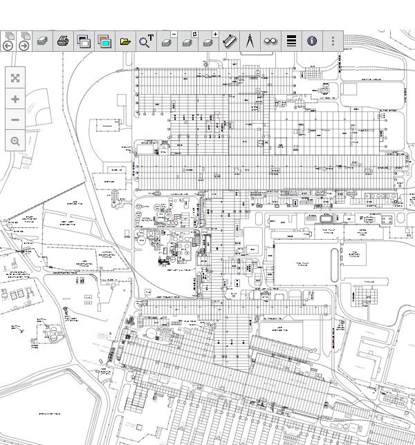
We shall declutter the AutoDesk sample file ‘Floor Plan Sample.dwg’. This sample shows a typical office building with cubicals and rooms each with desks, computers, phones, etc. All of this detail is not needed, so we will remove it.
This can be done using the PartOff command on the command line:
-PART_OFF="CHAIRS;CPU;EMPLOYEE;FURNITURE;PHONES;E-F-PLMB;E-F-CASE"
Adding all this to the command line can get quite long. However, it is likely that the layers to be turned off would not change much, so the use of a JSON parameter file would make sense. The command line could be:
-json=c:/your/path/layers_off.json
And the JSON file would be:
json { 'Layers' : { 'PartOff' : [ 'CHAIRS', 'CPU', 'EMPLOYEE', 'FURNITURE', 'PHONES', 'E-F-PLMB', 'E-F-CASE' ] } }
Almost all other parameters can be defined using a JSON parameter file, but something that is repetitive like turning layers off for a given function over a group of drawings is ideal for a JSON parameter file.
This would take the drawing from this:
To this:
You can download the sample drawing FloorPlan_Sample.dwg and the JSON FloorPlan_OffLayers.json to test it yourself with AutoXChange AX2024 .
Removing AutoCAD Blocks
Because AutoCAD Blocks tend to be placed on the special layer, 0, decluttering by simply turning layers off is not always sufficient. The Ignore Blocks (IB, BO, IGNORE_BLOCK[S]) parameter allows you to turn off processing of individual types of blocks. Block Names are separated by a semi-colon.
-IGNORE_BLOCKS=WOODEN;CEMENT;HEAD
You can download a sample drawing hq17_w_furniture.dwg. For test processing, use the parameter
-IG=A-FURN-FREE-E
Automatic Area/Name Matching
AutoXChange AX2024 Linkage Interface has the ability to automatically match certain area outlines and area names to create clickable areas on the SVG drawing. PDF has no direct equivalent. The same effect can be created in raster drawings via hotspot creation, where an external file is created with some sort of clickable region in raster coordinates. Many different methods of raster hotspots are possible.
Area/Name Matching relies on the drawing having the areas defined by closed polygons. Any of the three types of polylines (2D Polyline, Lightweight Polyline and 3D Polyline) can be used to define the closed polygons.
There are three modes of Matching:
1) Room Layer/Text Layer
2) Room Layer/Handle
3) Block Area/Name
Room Layer/Text Layer
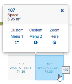
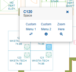
Many AutoCAD drawings, particularly those used for Facilities Management, will have close polygons defining the areas (usually rooms) on the drawing. This is called ‘polyganizing’ the drawing. These space polygons can be used to create automatic links from the drawing to an external data source such as a program or a database management system.
If the drawing has a room name or number, either as text on a given layer or as a block attribute with a given attribute tag (name), then the link can be established using the room number as the link key.
The Room Layer and Text Layer have to be defined using the -RL and -TL parameters, respectively. Text Layer processing works with either Simple Text or MText. Block Attributes can be used by defined the Attribute Tag using the -TAG parameter.
-RL=A-AREA -TL=A-IDEN -TAG=ATTRNAME
Example
This example is the basis of our automatic data linkage processing. The drawing has been setup for normal Archibus Facilities Management usage, where areas (rooms in this case) are defined on Layer RM$ and room names are defined on Layer RM$TXT. This is very standard for use with CAFM systems.
No actual links or clickable areas are defined, so we add them automatically. The following command line is used to process the file.
-i='hq17.dwg' -f=svg -RL=RM$ -TL=RM$TXT
You can download a sample drawing hq17.dwg. See the full Database Linkage parameter interface here.
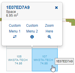
Room Layer/Handle
If the drawing has been polygonized as described above, but there are no room names or numbers (granted a minority of drawings), then the AutoCAD Handle can be used as the key. The Handle is a unique 16 digit hexidecimal identifier for every AutoCAD entity that does not change over the life of the drawing. The Handle is never reused even if the entity that used it is deleted.
For Room Layer/Handle processing, each closed polygon on the given (by -RL) layer is click-enabled using the handle of said polygon as the key. It is then up to the external datasource to have the polygon handles as the key to their data.
-RL=A-AREA -HB
See the full Database Linkage parameter interface here.
Block Area/Name
Block Area processing is mainly designed for use with mechanical parts, but can also be used with architectural drawings. Each Block Reference for the given Block Name has its extents calculated and an enclosing polygon added to the drawing with the Block Reference’s Handle as the key. In this manner it is easy to provide highlights of items like sinks, desks, etc or links to subparts of mechanical assemblies.
Example
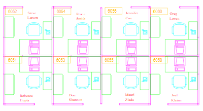
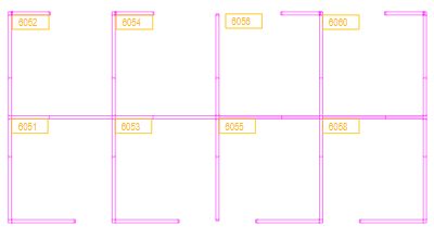
In this example a building has chairs defined in cubicals, among other equipment elsewhere. The chairs has data attributes assigned including an identifier named ‘ID’. This id will provide the link to the external datasource. We will convert each block instance to a SVG group with the geometry followed by an enclosing polygon. The polygon will have a specially defined attribute value for the ID.
The name of the block for the chairs is ‘SZT-ARM-2D’ and the name of the attribute tag is ‘ID’. The command line would be:
-i='hq17_w_attr.dwg' -svg -blockname='szt-arm-2d' -tltag=ID
When the SVG is brought into CADViewer it is now clickable and supports tooltips on hover. This functionality relies on custom extensions that are supported by AutoXChange and CADViewer and are therefore not displayed in normal browser-based SVG viewing.
You can download a sample drawing hq17_w_attr.dwg. See the full Database Linkage parameter interface here.
Using AutoXChange
AutoXChange is a command-line driven program where parameters are passed to control the conversion. The full technical documentation is available online.
In its simplest form two parameters are required: the input file and the output format. For instance:
ax2022 inputfile.dwg -svg
The first parameter will be used as the input filename if it does not start with a dash. Otherwise you can use -i to define the input filename. So the following is perfectly fine:
ax2022 -svg -i=inputfile.dwg
The output file name will default to the input filename with the extension changed to reflect the output format. For instance, converting to SVG will result in a default output filename of inputfile.svg. The output filename can be defined using the second parameter (if there is no dash) or -o.
ax2022 inputfile.dwg outputfile.svg -svg ax2022 -i=inputfile.dwg -o=outputfile.svg -svg
Some AutoXchange AX2024 parameters require additional information (such as the filenames above) while some are just switches and do not need additional information. If a parameter does require more information than the parameter name is followed by an equal sign and then the information. For instance, to set the Minimum Line Width you could use -lwmin=0.01, where the command is lwmin and the value is 0.01.
Download Article
Download this article: PreparingDrawings.pdf.
CADViewer - Tailor Made Software, Ltd.
Established in 1990, we’re a dedicated team of CAD experts and software developers that always have put our customers requirements into our products. Tailor Made Software, Ltd is the acknowledged leader in the Conversion, Extraction, Manipulation and Display of CAD Data. Since 1990 we have made ‘Write Once. View Anywhere’ not just a slogan, but a way of working.
Through our offices in Seattle in the Pacific Northwest in the US and in Stockholm, Sweden, we do our utmost to serve your needs on two Continents and around the World.
Contact Us Download Test your CAD drawings Online Quotation or Purchase Request