Adding interactivity to drawings, where moving the mouse over a drawing highlights areas or clicking on an area brings up data about the area, is a specialty of Tailor Made Software’s AutoXchange AX2024 and CADViewer. Usually this interactivity is added based on an AutoCAD DWG or MicroStation DGN drawing. However, it can also be added to some PDFs.
The ability to automatically add interactivity, via either MouseOver or MouseClick type events, is based on being able to identify the area and then add the proper mouse handlers. When dealing with an AutoCAD DWG or MicroStation DGN, the drawing can have many different identifiable areas, for instance:
- (1) Closed polylines enclosing the desired areas on a given layer
- (2) The extents of named blocks
- (3) Text notes on a given layer
With a PDF document you usually lose most of those. Depending on how the PDF was created it is likely that the CAD layering scheme will be lost on conversion to PDF. It is possible to mimic the layers using PDF Optional Content Groups, but that is usually not done. So the ability to do things based on layers (#1 and #3 above) is impaired. Similarly, there are no blocks in PDF, so that is not possible.
However, it can be possible to still use enclosing polylines and text ids to automatically recognize areas.
Tailor Made Software’s AutoXChange AX2024 will import PDF files maintaining the layering schema if present. If not it will import the drawing into three layers:
- (1) PDF_Geometry
- (2) PDF_Text
- (3) PDF_Solid Fills
See Automatic Area/Name Matching for how to use AutoXChange to automatically create mouse events with AutoCAD DWG drawings.
With PDF files that have areas (usually rooms on drawings, so we refer to this as “Room Layer”) that are polygonized, closed polylines that define the outline of each room, and text ids that define the “key” to the room, we can still automatically create highlighted regions. The “Room Layer” is PDF_Geometry and the “Text Layer” (the layer where the area ids is defined in text) is PDF_Text.
The AutoXChange AX2024 command would be:
-rl=PDF_Geometry -tl=PDF_Text
or
-roomlayer=PDF_Geometry -textlayer=PDF_Text
Obviously there may be many other text elements that are not valid room ids and other polylines that are not valid room outlines. To try to alleviate this there are several optimizations that are applied.
-
(1) Only the smallest outline that contains the text is used. This means that a room outline will be used instead of an outline of a section of the building.
-
(2) If there are several text elements inside a room outline, the “northern most” (the one towards the top of the drawing) will be used. This can be modified on a custom basis.
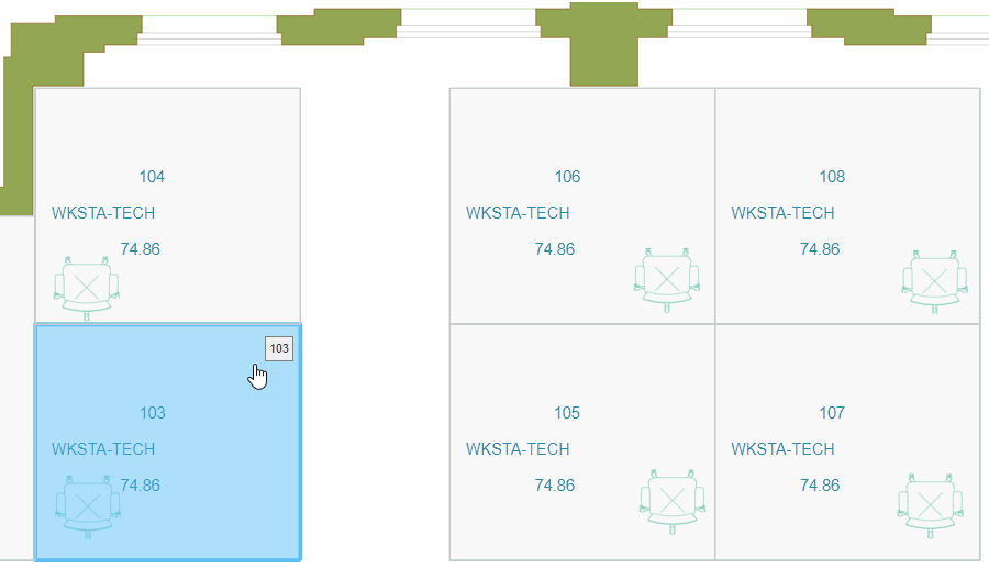
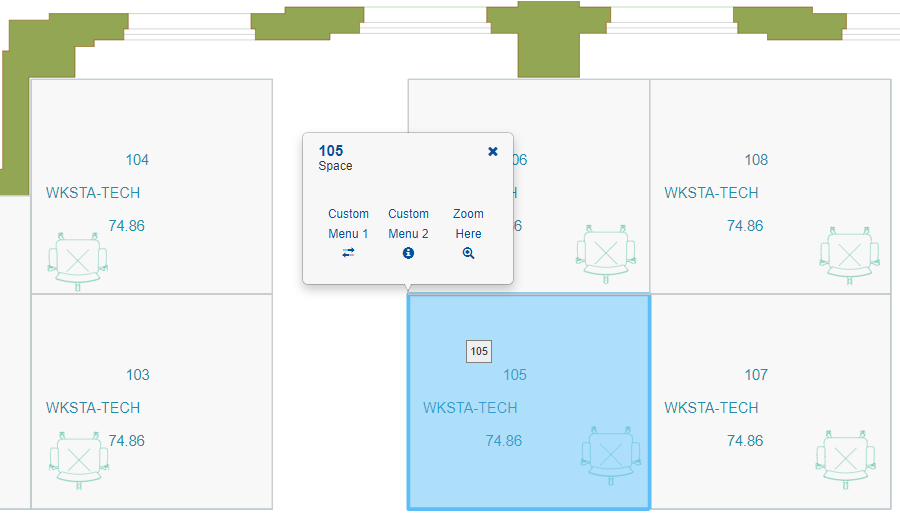
The PDF drawing displayed in CADViewer:
Removing Clutter
If there is too much clutter in the resulting SVG file the easy solution is to:
- (1) Save the intermediate DWG file
- (2) Use AutoCAD or a clone (we typically use Draftsite) to remove any unwanted elements in the file
- (3) Convert the DWG to SVG applying Room Layer/Text Layer (RL/TL) on that step
When AutoXChange converts from PDF to another format it creates an internal AutoCAD DWG from the PDF. It then processes that DWG just as it would any other DWG and produces the output format. Currently we do not have DWG or DXF as normal output formats, but we will probably add that in the future where the end result would be a DWG or DXF file instead of a SVG, PDF or raster format. For now, use the -savedwg parameter to save this intermediate DWG file.
ax2022 <inputfile> -svg -savedwg
Until such time as we add -dwg and -dxf as output formats, you have to list another format, usually -svg, when you do a conversion. If all you want is the DWG file, then you can ignore the SVG. Note that setting the output file name only affects the name of the SVG, not the name of the intermediate file. It will be call
After modifying the elements in the DWG you then convert it to SVG adding the RL/TL processing. See the article “How to Prepare Drawings” for more information but the basic example command line is:
ax2022 <inputfile> -svg -rl=PDF_Geometry -tl=PDF_Text
Setting the parameters in CADViewer
The conversion parameters can also be set dynamically in CADViewer, please see Settings.
At initialization of CADViewer, the conversion parameters can also be added through the API method cvjs_conversion_addAXconversionParameter(), see Initialize and Load Drawing.
Do Download the Article and the test drawing, hq17.pdf!